Read this model as text
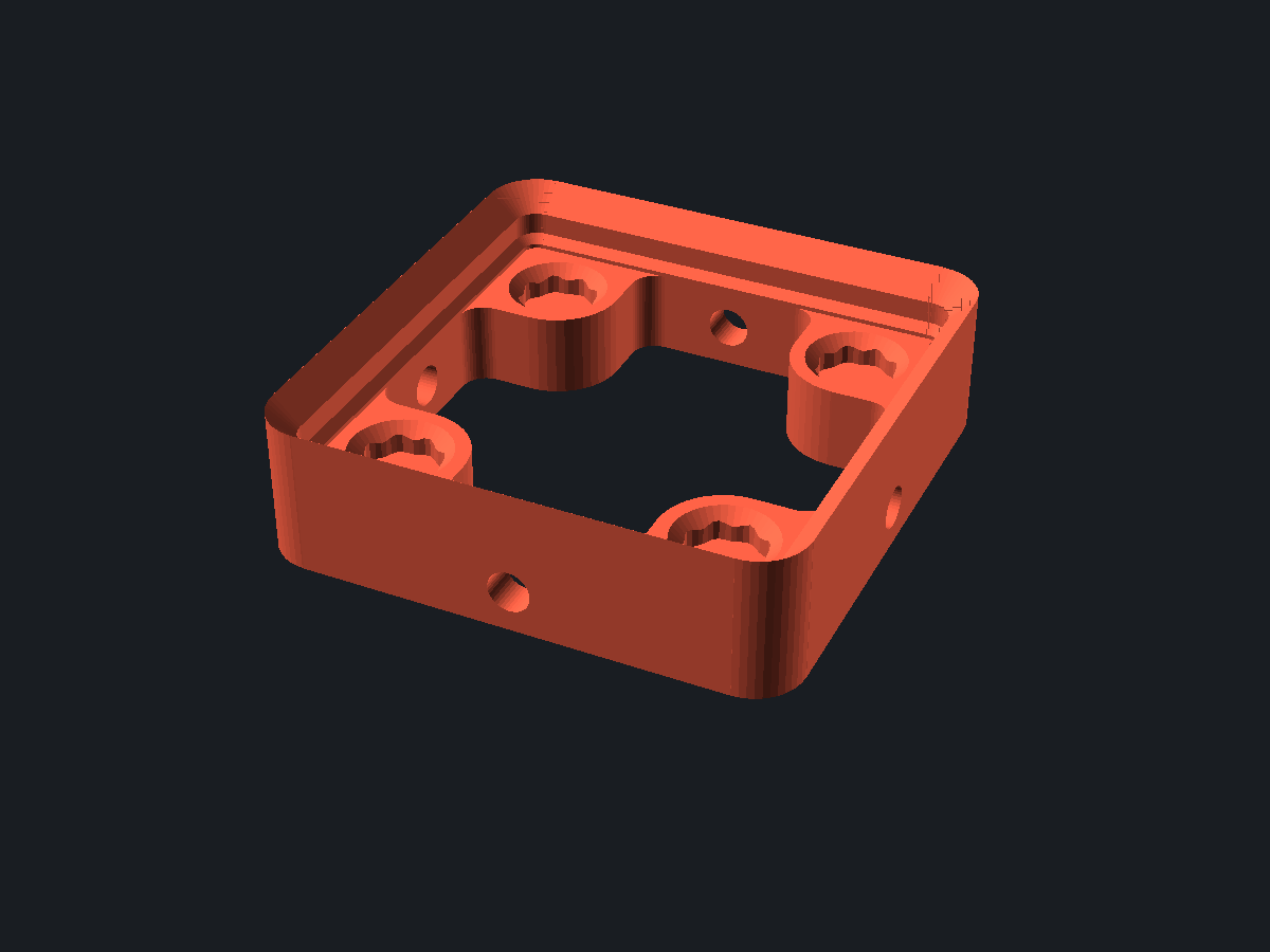
The plate the bins sit in. It tiles the 42 mm Gridfinity grid and comes in several styles, from a thin plain plate up to one with screw holes, magnet holes and a skeletonised underside.
The image shows the solid OpenSCAD renders at n_screws 1 · fitx 0 · fity 0 · enable_magnet true · crush_ribs true · chamfer_holes true.
Gridfinity baseplate
remixcad/gridfinity-baseplate@1.0.0
Report
For a legal or policy problem: a license violation, personal data, somebody else’s work republished as their own. A model that prints badly is a comment, not a report.
Parameters
from sourceDescription
What is this
The plate the bins sit in. It tiles the 42 mm Gridfinity grid and comes in several styles, from a thin plain plate up to one with screw holes, magnet holes and a skeletonised underside.
What you use it for
Line a drawer, a shelf or a workbench with it, then drop bins on top. Size it to the space you have; it does not have to be a whole number of bins wider than what it holds.
Design notes
The plate can be made slightly larger than the nominal grid with the fit and distance settings, which is what you want when it has to drop into a drawer that is not an exact multiple of 42 mm.
Parameters
gridx and gridy give the footprint in 42 mm units. style_plate picks how much material and hardware the plate carries. d_screw and n_screws set the mounting holes, and the fit and distance settings pad the outside.
Use with your agent
{
  "mcpServers": {
    "remixcad": {
      "type": "http",
      "url": "https://remix-cad.vercel.app/api/mcp"
    }
  }
}get_model("remixcad/gridfinity-baseplate@1.0.0")Returns the manifest, the source, the import closure and the license obligations. Full MCP setup.
Parameter table
Parsed from the Customizer annotations in main.scad| Name | Default | Range | Unit | Description |
|---|---|---|---|---|
| gridx | 1 | units | Width in grid units of 42 mm. | |
| gridy | 1 | units | Depth in grid units of 42 mm. | |
| d_screw | 3.35 | mm | Screw hole diameter for mounting the plate down. | |
| d_screw_head | 5 | |||
| n_screws | 1 | 1 to 3 | ||
| distancex | 0 | |||
| distancey | 0 | |||
| fitx | 0 | -1 to 1 step 0.1 | ||
| fity | 0 | -1 to 1 step 0.1 | ||
| style_plate | 3 | |||
| style_hole | 0 | |||
| enable_magnet | true | |||
| crush_ribs | true | |||
| chamfer_holes | true |
Lineage
0 models depend on this oneOnly what this model came from and what came from it.
License
Whoever downloads this takes these obligations along- remixcad/gridfinity-baseplate@1.0.0 is MIT
- remixcad/gridfinity-core@1.0.0 is MIT
- @File gridfinity-baseplate.scad @Brief Functions and standards to make a SINGLE gridfinity baseplate. @Copyright Arthur Moore 2025 MIT License @WARNING: Where possible, `use` thise file. Constants may change between minor versions. /
- remixcad/threads@1.0.0 is CC0
Source
main.scad is the entrypointmain.scad
// ===== INFORMATION ===== //
/*
 IMPORTANT: rendering will be better in development builds and not the official release of OpenSCAD, but it makes rendering only take a couple seconds, even for comically large bins.

https://github.com/kennetek/gridfinity-rebuilt-openscad

*/

include <remixcad/gridfinity-core/src/core/standard.scad>
include <remixcad/gridfinity-core/src/core/gridfinity-baseplate.scad>
use <remixcad/gridfinity-core/src/core/gridfinity-rebuilt-utility.scad>
use <remixcad/gridfinity-core/src/core/gridfinity-rebuilt-holes.scad>
use <remixcad/gridfinity-core/src/helpers/generic-helpers.scad>
use <remixcad/gridfinity-core/src/helpers/grid.scad>

// ===== PARAMETERS ===== //

/* [Setup Parameters] */
$fa = 8;
$fs = 0.25;

/* [General Settings] */
// number of bases along x-axis
gridx = 1;
// number of bases along y-axis
gridy = 1;

/* [Screw Together Settings - Defaults work for M3 and 4-40] */
// screw diameter
d_screw = 3.35;
// screw head diameter
d_screw_head = 5;
// screw spacing distance
screw_spacing = .5;
// number of screws per grid block
n_screws = 1; // [1:3]


/* [Fit to Drawer] */
// minimum length of baseplate along x (leave zero to ignore, will automatically fill area if gridx is zero)
distancex = 0;
// minimum length of baseplate along y (leave zero to ignore, will automatically fill area if gridy is zero)
distancey = 0;

// where to align extra space along x
fitx = 0; // [-1:0.1:1]
// where to align extra space along y
fity = 0; // [-1:0.1:1]


/* [Styles] */

// baseplate styles
style_plate = 3; // [0: thin, 1:weighted, 2:skeletonized, 3: screw together, 4: screw together minimal]


// hole styles
style_hole = 0; // [0:none, 1:countersink, 2:counterbore]

/* [Magnet Hole] */
// Baseplate will have holes for 6mm Diameter x 2mm high magnets.
enable_magnet = true;
// Magnet holes will have crush ribs to hold the magnet.
crush_ribs = true;
// Magnet holes will have a chamfer to ease insertion.
chamfer_holes = true;

hole_options = bundle_hole_options(refined_hole=false, magnet_hole=enable_magnet, screw_hole=false, crush_ribs=crush_ribs, chamfer=chamfer_holes, supportless=false);

// ===== IMPLEMENTATION ===== //

color("tomato")
gridfinityBaseplate([gridx, gridy], l_grid, [distancex, distancey], style_plate, hole_options, style_hole, [fitx, fity]);

// ===== CONSTRUCTION ===== //

/**
 * @brief Create a baseplate.
 * @param grid_size_bases Number of Gridfinity bases.
 *        2d Vector. [x, y].
 *        Set to [0, 0] to auto calculate using min_size_mm.
 * @param length X,Y size of a single Gridfinity base.
 * @param min_size_mm Minimum size of the baseplate. [x, y]
 *                    Extra space is filled with solid material.
 *                    Enables "Fit to Drawer."
 * @param sp Baseplate Style
 * @param hole_options
 * @param sh Style of screw hole allowing the baseplate to be mounted to something.
 * @param fit_offset Determines where padding is added.
 */
module gridfinityBaseplate(grid_size_bases, length, min_size_mm, sp, hole_options, sh, fit_offset = [0, 0]) {

    assert(is_list(grid_size_bases) && len(grid_size_bases) == 2,
        "grid_size_bases must be a 2d list");
    assert(is_list(min_size_mm) && len(min_size_mm) == 2,
        "min_size_mm must be a 2d list");
    assert(is_list(fit_offset) && len(fit_offset) == 2,
        "fit_offset must be a 2d list");
    assert(grid_size_bases.x > 0 || min_size_mm.x > 0,
        "Must have positive x grid amount!");
    assert(grid_size_bases.y > 0 || min_size_mm.y > 0,
        "Must have positive y grid amount!");

    additional_height = calculate_offset(sp, hole_options[1], sh);

    // Final height of the baseplate. In mm.
    baseplate_height_mm = additional_height + BASEPLATE_HEIGHT;

    // Final size in number of bases
    grid_size = [for (i = [0:1])
        grid_size_bases[i] == 0 ? floor(min_size_mm[i]/length) : grid_size_bases[i]];

    // Final size of the base before padding. In mm.
    grid_size_mm = concat(grid_size * length, [baseplate_height_mm]);

    // Final size, including padding. In mm.
    size_mm = [
        max(grid_size_mm.x, min_size_mm.x),
        max(grid_size_mm.y, min_size_mm.y),
        baseplate_height_mm
    ];

    // Amount of padding needed to fit to a specific drawer size. In mm.
    padding_mm = size_mm - grid_size_mm;

    is_padding_needed = padding_mm != [0, 0, 0];

    //Convert the fit offset to percent of how much will be added to the positive axes.
    // -1 : 1 -> 0 : 1
    fit_percent_positive = [for (i = [0:1]) (fit_offset[i] + 1) / 2];

    padding_start_point = -grid_size_mm/2 -
        [
            padding_mm.x * (1 - fit_percent_positive.x),
            padding_mm.y * (1 - fit_percent_positive.y),
            -grid_size_mm.z/2
        ];

    corner_points = [
        padding_start_point + [size_mm.x, size_mm.y, 0],
        padding_start_point + [0, size_mm.y, 0],
        padding_start_point,
        padding_start_point + [size_mm.x, 0, 0],
    ];

    echo(str("Number of Grids per axes (X, Y)]: ", grid_size));
    echo(str("Final size (in mm): ", size_mm));
    if (is_padding_needed) {
        echo(str("Padding +X (in mm): ", padding_mm.x * fit_percent_positive.x));
        echo(str("Padding -X (in mm): ", padding_mm.x * (1 - fit_percent_positive.x)));
        echo(str("Padding +Y (in mm): ", padding_mm.y * fit_percent_positive.y));
        echo(str("Padding -Y (in mm): ", padding_mm.y * (1 - fit_percent_positive.y)));
    }

    screw_together = sp == 3 || sp == 4;
    minimal = sp == 0 || sp == 4;

    difference() {
        union() {
            // Baseplate itself
            difference() {
                translate(padding_start_point)
                cube(size_mm);
                // Replicated Single Baseplate piece
                pattern_grid(grid_size, [length, length], true, true) {
                    if (minimal) {
                        translate([0, 0, -TOLLERANCE/2])
                        baseplate_cutter([length, length], baseplate_height_mm+TOLLERANCE);
                    } else {
                        translate([0, 0, additional_height+TOLLERANCE/2])
                        baseplate_cutter([length, length]);

                        // Bottom/through pattern for the solid baseplates.
                        if (sp == 1) {
                            cutter_weight();
                        } else if (sp == 2 || sp == 3) {
                            translate([0,0,-TOLLERANCE])
                            linear_extrude(additional_height + (2 * TOLLERANCE))
                            profile_skeleton();
                        }

                        // Add holes to the solid baseplates.
                        hole_pattern(){
                            // Manget hole
                            translate([0, 0, additional_height+TOLLERANCE])
                            mirror([0, 0, 1])
                            block_base_hole(hole_options);

                            translate([0,0,-TOLLERANCE])
                            if (sh == 1) {
                                cutter_countersink();
                            } else if (sh == 2) {
                                cutter_counterbore();
                            }
                        }
                    }
                }
            }
        }

        // Round the outside corners (Including Padding)
        for(i = [0:len(corner_points) - 1]) {
                point = corner_points[i];
                translate([
                point.x + (BASEPLATE_OUTER_RADIUS * -sign(point.x)),
                point.y + (BASEPLATE_OUTER_RADIUS * -sign(point.y)),
                0
            ])
            rotate([0, 0, i*90])
            square_baseplate_corner(additional_height, true);
        }

        if (screw_together) {
            translate([0, 0, additional_height/2])
            cutter_screw_together(grid_size.x, grid_size.y, length);
        }
    }
}

function calculate_offset(style_plate, enable_magnet, style_hole) =
    assert(style_plate >=0 && style_plate <=4)
    let (screw_together = style_plate == 3 || style_plate == 4)
    screw_together ? 6.75 :
    style_plate==0 ? 0 :
    style_plate==1 ? bp_h_bot :
    calculate_offset_skeletonized(enable_magnet, style_hole);

function calculate_offset_skeletonized(enable_magnet, style_hole) =
    h_skel + (enable_magnet ? MAGNET_HOLE_DEPTH : 0) +
    (
        style_hole==0 ? d_screw :
        style_hole==1 ? BASEPLATE_SCREW_COUNTERSINK_ADDITIONAL_RADIUS : // Only works because countersink is at 45 degree angle!
        BASEPLATE_SCREW_COUNTERBORE_HEIGHT
    );

module cutter_weight() {
    union() {
        linear_extrude(bp_cut_depth*2,center=true)
        square(bp_cut_size, center=true);
        pattern_circular(4)
        translate([0,10,0])
        linear_extrude(bp_rcut_depth*2,center=true)
        union() {
            square([bp_rcut_width, bp_rcut_length], center=true);
            translate([0,bp_rcut_length/2,0])
            circle(d=bp_rcut_width);
        }
    }
}
module hole_pattern(){
    pattern_circular(4)
    translate([l_grid/2-d_hole_from_side, l_grid/2-d_hole_from_side, 0]) {
        render();
        children();
    }
}

module cutter_countersink(){
    screw_hole(SCREW_HOLE_RADIUS + TOLLERANCE, 2*BASE_PROFILE_HEIGHT,
        false, BASEPLATE_SCREW_COUNTERSINK_ADDITIONAL_RADIUS);
}

module cutter_counterbore(){
    screw_radius = SCREW_HOLE_RADIUS + TOLLERANCE;
    counterbore_height = BASEPLATE_SCREW_COUNTERBORE_HEIGHT + 2*LAYER_HEIGHT;
    union(){
        cylinder(h=2*BASE_PROFILE_HEIGHT, r=screw_radius);
        difference() {
            cylinder(h = counterbore_height, r=BASEPLATE_SCREW_COUNTERBORE_RADIUS);
            make_hole_printable(screw_radius, BASEPLATE_SCREW_COUNTERBORE_RADIUS, counterbore_height);
        }
    }
}

/**
 * @brief Added or removed from the baseplate to square off or round the corners.
 * @param height Baseplate's height, excluding lip and clearance height.
 * @param subtract If the corner should be scaled to allow subtraction.
 */
module square_baseplate_corner(height=0, subtract=false) {
    assert(height >= 0);
    assert(is_bool(subtract));

    subtract_ammount = subtract ? TOLLERANCE : 0;

    translate([0, 0, -subtract_ammount])
    linear_extrude(height + BASEPLATE_HEIGHT + (2 * subtract_ammount))
    difference() {
        square(BASEPLATE_OUTER_RADIUS + subtract_ammount , center=false);
        // TOLLERANCE needed to prevent a gap
        circle(r=BASEPLATE_OUTER_RADIUS - TOLLERANCE);
    }
}

/**
 * @brief 2d Cutter to skeletonize the baseplate.
 * @param size Width/Length of a single baseplate.  Only set if deviating from the standard!
 * @example difference(){
 *              cube(large_number);
 *              linear_extrude(large_number+TOLLERANCE)
 *              profile_skeleton();
 *          }
 */
module profile_skeleton(size=l_grid) {
    l = baseplate_inner_size([size, size]).x;

    offset(r_skel)
    difference() {
        square(l-2*r_skel, center = true);

        hole_pattern()
        offset(MAGNET_HOLE_RADIUS+r_skel+2)
        square([l,l]);
    }
}

module cutter_screw_together(gx, gy, size = l_grid) {

    screw(gx, gy);
    rotate([0,0,90])
    screw(gy, gx);

    module screw(a, b) {
        copy_mirror([1,0,0])
        translate([a*size/2, 0, 0])
        pattern_grid([1, b], [1, size], true, true)
        pattern_grid([1, n_screws], [1, d_screw_head + screw_spacing], true, true)
        rotate([0,90,0])
        cylinder(h=size/2, d=d_screw, center = true);
    }
}
Comments
Context, not a score. Comments never move a model up or down the results.No comments yet
Printed it? A note about your material and the clearance you landed on saves the next person a failed print.