Read this model as text
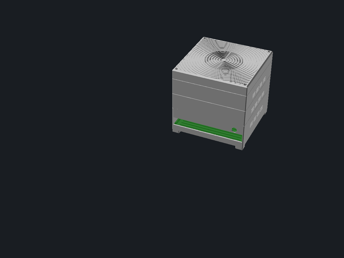
A stackable case for a Mini-ITX NAS board, sized so every part prints on a 180 mm bed (Bambu A1 mini). The stack is a base module that carries the board on a ledge, bay modules with a bolt grid in the floor that take drive trays or anything else you design for the grid, and a slim lid with a relief pattern across its whole top that opens into a grille over the fan and pulls air up through the stack. Modules locate on each other with a lip and pocket and bolt together with M3 screws into captive nuts. test_print renders a coupon set to check every fit in about an hour: the rear left corner of the board module, of a bay module and of the lid, the matching end of the rear shield and one foot.
The image shows the solid OpenSCAD renders at part assembly · test_print false · test_size 36.8 · bay_modules 2 · hang_hdd true · hang_rot true · explode 0 · show_hardware true · board 170 · board_clear 0.5 · ledge_w 2 · ledge_h 6.5 · board_lip true · lip_over 2 · side_relief right · relief_y0 110 · relief_y1 168 · board_h 60 · front_clear 2 · front_relief true · psu_x0 105 · psu_x1 170 · button_d 16 · button_x 88 · button_z 36 · button_ring true · jack_d 12 · jack_pos rear · jack_x 150 · jack_z 42 · vents true · vent_style horizontal · vent_span 96 · vent_z 8 · vent_z_board 28 · vent_w 1.6 · vent_rows 3 · vent_dash 20 · vent_h 12 · vent_pitch 6 · hdd_w 101.6 · hdd_l 147 · hdd_h 26.1 · hdd_gap 2 · grid_boss_h 2 · tray_t 2.5 · tray_col 1 · hang_col 0 · fan_size 92 · fan_t 14 · fan_gap 4 · lid_pattern ripple · lid_relief 1 · lid_ch 2.5 · io_x 0 · io_w 170 · io_h 20 · wall 3 · floor_t 2.5 · top_t 2.5 · corner_r 2 · edge_ch 0.8 · lip_h 4 · lip_t 1.5 · lip_c 0.2 · nut_af 5.7 · foot_h 8 · color_case Silver.
Stackable Mini-ITX NAS case
mick/itx-nas-stack@1.16.0
Report
For a legal or policy problem: a license violation, personal data, somebody else’s work republished as their own. A model that prints badly is a comment, not a report.
Parameters
from sourceDescription
What is this
A stackable case for a Mini-ITX NAS board, sized so every part prints on a 180 mm bed (Bambu A1 mini). The stack is a base module that carries the board on a ledge, bay modules with a bolt grid in the floor that take drive trays or anything else you design for the grid, and a slim lid with a relief pattern across its whole top that opens into a grille over the fan and pulls air up through the stack. Modules locate on each other with a lip and pocket and bolt together with M3 screws into captive nuts. test_print renders a coupon set to check every fit in about an hour: the rear left corner of the board module, of a bay module and of the lid, the matching end of the rear shield and one foot.
What you use it for
A slim, clean NAS around a 170 × 170 board with a pico PSU: DC barrel jack in the rear shield just above the ports (or in a side wall), a centred 16 mm vandal switch in the front, the rear I/O open above the board with a flat rear shield that slides down into grooves. The board rests on a narrow ledge along all four walls, so it fits any 170 mm board regardless of its hole pattern, and is held without screws: a lip over its front edge, a rear strip that rises to just under the ports, and the shield whose port cutouts capture the rear. Each bay module is 39 mm tall around a 26 mm drive and has a grid of 72 bosses on an 18 mm pitch; the 3.5" tray screws to the drive's bottom holes with standard 6-32 drive screws and bolts down on any four bosses with M3 × 8, in any grid column, so the rest of the bay is free for a second tray, an SSD, a fan or whatever fits 18 mm steps. The grid holes go through the floor, so the hanging tray bolts a second drive upside down under the same floor, into the free air above a low CPU cooler in the board module; turned sideways it stays clear of the pico PSU in the front corner and its connector lands next to the board's SATA ports. The lid is 23 mm tall around a 92 × 14 mm slim fan (Noctua NF-A9x14 or similar); a 25 mm fan adds 11 mm. Screw-on feet with a recess for a rubber pad lift the base module for air under the floor. A rear cutout in every floor passes the SATA cables down to the board.
Design notes
Print everything without supports. Every overhang is 45° or less and every bridge is 20 mm or less: the boss pyramids, the nut slots, the pocket groove, the floor cells between ribs, the vent dashes and the wedge under the board lip are all shaped for that; a slicer set to its default 30° threshold will still offer to fill them, and that support is hard to get out. All x positions are measured from the left as seen from the rear, the I/O side. The footprint is board + clearance + two walls, 177 mm by default, plus front_clear in depth for the pico PSU that overhangs the front edge; the front wall is thinned to 1.2 mm over the PSU, and a side wall can be thinned the same way where a connector overhangs the board edge. Every millimetre of front_clear counts against the 180 mm bed. The board goes in front edge first, under the lip, and the rear is lowered onto the ledge behind the raised rear strip; the lip stops the front lifting, the strip stops the board sliding back, the shield stops the rear lifting. The lip is left out over the PSU span so it cannot touch the 24-pin header, and carries a 45° wedge underneath across the clearance gap. Every module has a pocket ring under its floor and a lip ring on top; the lip is the inner half of the wall so the outside stays flush, and a chamfer on the top edge draws a seam line at every joint; the lid carries a deeper chamfer so it reads as a cap. Air enters through a band of short horizontal dashes on each side of every module and leaves through the lid; the drive sits 2 mm under the next floor, whose rib zone adds another 4 mm of air over it, and 2 mm bosses under the tray keep the slots open under the drive. The lid is plate, 2.5 mm bosses, the fan, and fan_gap of air under it, nothing more. The lid top is one pattern: ripples spreading from the fan, a honeycomb, or diagonal lines, as raised tiles with a recessed groove network everywhere, and the same pattern cut through over the fan only, because a fan only pulls air through the stack when the rest of the lid is closed. The fan hangs from four bosses under the top plate and screws from the inside before the lid goes on. The floor of every module sits on a rib grid; the hanging tray carries pads that reach up between those ribs to the floor. The coupons are cut on a rib line, so nothing in them bridges further than in the real parts. Four bosses hang in the top corners of every module, each with a side slot that traps an M3 nut under 2.5 mm of material. The feet follow the case corner, plug into the corner cells of the rib grid and bolt through the same floor holes. Bolts: M3 × 12 between modules, for the feet and for the hanging tray, M3 × 25 for the lid, M3 × 16 for a 14 mm fan (fan_t plus 2 for other fans), M3 × 8 for trays, 6-32 for the drive. Tolerances are tuned for PETG on an A1 mini: 0.2 mm on the lip, 0.5 mm around the board, 0.3 mm in holes, 0.2 mm on nuts.
Parameters
test_print swaps whatever part is chosen for the coupon set, test_size is the corner it cuts. part picks the assembly or one printable part in print orientation. hang_hdd shows a drive hanging under the lowest bay, hang_rot turns it sideways. ledge_w and ledge_h size the ledge; board_lip and lip_over set the lip over the front edge; side_relief, relief_y0 and relief_y1 thin a side wall over an overhanging connector. board_h sets the height of the board module. front_clear adds depth in front of the board, front_relief and psu_x0/psu_x1 thin the front wall over the PSU. button_d/x/z place the switch, button_ring recesses a ring around it. jack_pos puts the DC jack in the rear shield or a side wall, jack_x/jack_z place it. vent_style, vent_span, vent_rows, vent_dash, vent_z, vent_z_board, vent_w and vent_pitch shape the intake bands. hdd_w/l/h size the drive and tray, hdd_gap the air above it, grid_boss_h the height of the floor grid, tray_t the tray, tray_col the grid column of the bay tray; together they set the bay height. fan_size picks the fan (0 for a plain lid), fan_t its thickness, fan_gap the air under it; together they set the lid height. lid_pattern picks the relief, lid_relief its depth, lid_ch the lid chamfer. io_x/io_w/io_h cut one opening in the rear shield. wall, lip_h, lip_t, lip_c and edge_ch tune the fit and the seam between modules; nut_af is the nut size across flats, foot_h the height of the feet.
Use with your agent
{
  "mcpServers": {
    "remixcad": {
      "type": "http",
      "url": "https://remix-cad.vercel.app/api/mcp"
    }
  }
}get_model("mick/itx-nas-stack@1.16.0")Returns the manifest, the source, the import closure and the license obligations. Full MCP setup.
Parameter table
Parsed from the Customizer annotations in main.scad| Name | Default | Range | Unit | Description |
|---|---|---|---|---|
| part | "assembly" | assembly, board_module, bay_module, tray_35, tray_35_hanging, lid, rear_shield, foot | ||
| test_print | false | |||
| test_size | 36.8 | 18.8 to 54.8 step 18 | ||
| bay_modules | 2 | 0 to 4 step 1 | ||
| hang_hdd | true | |||
| hang_rot | true | |||
| explode | 0 | 0 to 80 step 5 | ||
| show_hardware | true | |||
| board | 170 | 120 to 172 step 1 | ||
| board_clear | 0.5 | 0.3 to 1.5 step 0.1 | ||
| ledge_w | 2 | 1.5 to 4 step 0.1 | ||
| ledge_h | 6.5 | 4 to 10 step 0.5 | ||
| board_lip | true | |||
| lip_over | 2 | 1 to 4 step 0.5 | ||
| side_relief | "right" | none, right, left | ||
| relief_y0 | 110 | 5 to 170 step 1 | ||
| relief_y1 | 168 | 5 to 175 step 1 | ||
| board_h | 60 | 40 to 90 step 1 | ||
| front_clear | 2 | 0 to 10 step 0.5 | ||
| front_relief | true | |||
| psu_x0 | 105 | 0 to 160 step 1 | ||
| psu_x1 | 170 | 10 to 170 step 1 | ||
| button_d | 16 | 0 to 22 step 0.5 | ||
| button_x | 88 | 10 to 167 step 0.5 | ||
| button_z | 36 | 15 to 80 step 1 | ||
| button_ring | true | |||
| jack_d | 12 | 0 to 16 step 0.5 | ||
| jack_pos | "rear" | rear, right, left | ||
| jack_x | 150 | 10 to 160 step 1 | ||
| jack_z | 42 | 12 to 80 step 1 | ||
| vents | true | |||
| vent_style | "horizontal" | horizontal, vertical | ||
| vent_span | 96 | 30 to 150 step 2 | ||
| vent_z | 8 | 6 to 20 step 1 | ||
| vent_z_board | 28 | 6 to 50 step 1 | ||
| vent_w | 1.6 | 1.2 to 4 step 0.2 | ||
| vent_rows | 3 | 1 to 6 step 1 | ||
| vent_dash | 20 | 8 to 40 step 1 | ||
| vent_h | 12 | 6 to 30 step 1 | ||
| vent_pitch | 6 | 4 to 12 step 0.5 | ||
| hdd_w | 101.6 | 69 to 102 step 0.1 | ||
| hdd_l | 147 | 100 to 150 step 0.1 | ||
| hdd_h | 26.1 | 7 to 30 step 0.1 | ||
| hdd_gap | 2 | 2 to 10 step 0.5 | ||
| grid_boss_h | 2 | 2 to 5 step 0.5 | ||
| tray_t | 2.5 | 2.5 to 4 step 0.1 | ||
| tray_col | 1 | 0 to 2 step 1 | ||
| hang_col | 0 | 0 to 2 step 1 | ||
| fan_size | 92 | 0, 40, 60, 80, 92, 120 | ||
| fan_t | 14 | 10 to 30 step 1 | ||
| fan_gap | 4 | 2 to 15 step 1 | ||
| lid_pattern | "ripple" | ripple, hex, diagonal | ||
| lid_relief | 1 | 0 to 1.5 step 0.2 | ||
| lid_ch | 2.5 | 0 to 4 step 0.5 | ||
| io_x | 0 | 0 to 170 step 0.5 | ||
| io_w | 170 | 10 to 170 step 0.5 | ||
| io_h | 20 | 5 to 60 step 0.5 | ||
| wall | 3 | 2.5 to 4 step 0.1 | ||
| floor_t | 2.5 | 2 to 4 step 0.1 | ||
| top_t | 2.5 | 2 to 4 step 0.1 | ||
| corner_r | 2 | 0 to 3 step 0.5 | ||
| edge_ch | 0.8 | 0 to 1.5 step 0.1 | ||
| lip_h | 4 | 3 to 6 step 0.5 | ||
| lip_t | 1.5 | 1.2 to 2 step 0.1 | ||
| lip_c | 0.2 | 0.1 to 0.4 step 0.05 | ||
| nut_af | 5.7 | 5.4 to 6.2 step 0.1 | ||
| foot_h | 8 | 5 to 15 step 0.5 | ||
| color_case | "Silver" | Silver, Gainsboro, White, DimGray, Black, SlateGray, FireBrick, SteelBlue, ForestGreen, Goldenrod |
Lineage
0 models depend on this oneOnly what this model came from and what came from it.
License
Whoever downloads this takes these obligations along- mick/itx-nas-stack@1.16.0 is MIT
Source
main.scad is the entrypointmain.scad
// Stackable Mini-ITX NAS case for a small printer (180 mm bed).
// A base module carries the board on a ledge, bay modules carry drive trays on a
// bolt grid, and a fan lid closes the stack and pulls air up through it. Modules
// print upright as one piece, the lid prints upside down, the shield, trays and feet
// flat. Modules bolt together with M3 screws into nuts trapped in corner bosses.
// Everything prints without supports.
//
// Coordinates: y = 0 is the rear (I/O) wall, x = 0 the left wall AS SEEN FROM THE
// REAR. Every x position in the parameters follows that view.

/* [Parts] */
// The whole stack, or one part in print orientation.
part = "assembly"; // [assembly, board_module, bay_module, tray_35, tray_35_hanging, lid, rear_shield, foot]
// Print a coupon set instead: the rear left corner of the board module, of a bay
// module and of the lid (upside down, as it prints), the matching strip of rear
// shield and one foot. Stack them, drop a nut in, bolt through, slide the shield in:
// every fit is tested in about an hour.
test_print = false;
// Size of the corner the coupons are cut from. On a rib line (18.8, 36.8, 54.8) so
// the cut floor edge sits on a rib instead of hanging in the air.
test_size = 36.8; // [18.8:18:54.8]
// Bay modules shown in the assembly.
bay_modules = 2; // [0:1:4]
// Show a drive hanging under the lowest bay, above the board.
hang_hdd = true;
// Turn the hanging drive sideways, connector toward the right wall: clears the pico
// PSU in the front right corner and lands next to the SATA ports.
hang_rot = true;
// Pull the stack apart in the assembly view.
explode = 0; // [0:5:80]
// Show the board and the drives as ghosts in the assembly.
show_hardware = true;

/* [Board] */
// Board size, 170 for Mini-ITX.
board = 170; // [120:1:172]
// Gap between the board edge and the wall, each side.
board_clear = 0.5; // [0.3:0.1:1.5]
// The board rests on a narrow ledge along all four walls: width, and height above the floor.
ledge_w = 2; // [1.5:0.1:4]
ledge_h = 6.5; // [4:0.5:10]
// Hold the board without screws: a lip over its front edge, a rear strip raised to
// just under the ports, and the shield capturing the ports. Slide the front edge under
// the lip, lower the rear. The lip is left out over the PSU span.
board_lip = true;
// How far the lip reaches over the board.
lip_over = 2; // [1:0.5:4]
// Thin a side wall to 1.2 mm where a connector overhangs the board edge, between
// relief_y0 and relief_y1 from the rear, from the board up 12 mm.
side_relief = "right"; // [none, right, left]
relief_y0 = 110; // [5:1:170]
relief_y1 = 168; // [5:1:175]
// Height of the board module. With a hanging drive the cooler gets board_h minus 44 mm.
board_h = 60; // [40:1:90]

/* [Front, rear and sides] */
// Extra depth in front of the board for the pico PSU that overhangs the front edge.
// Every millimetre adds to the 177 mm footprint; an A1 mini bed stops at 180.
front_clear = 2; // [0:0.5:10]
// Thin the front wall to 1.2 mm over the PSU, between psu_x0 and psu_x1 from the
// left as seen from the rear. On this board the PSU sits at the SATA side, the right.
front_relief = true;
psu_x0 = 105; // [0:1:160]
psu_x1 = 170; // [10:1:170]
// Thread diameter of the power button, 16 for the common vandal switch. 0 for none.
button_d = 16; // [0:0.5:22]
// Button position from the left, and height from the module bottom. 88 is centred.
button_x = 88; // [10:0.5:167]
button_z = 36; // [15:1:80]
// Shallow ring recessed around the button.
button_ring = true;
// Panel mount DC jack hole, 0 for none.
jack_d = 12; // [0:0.5:16]
// Where the DC jack sits: in the rear shield above the ports, or in a side wall.
jack_pos = "rear"; // [rear, right, left]
// Jack position: from the left as seen from the rear (rear), or from the rear (sides).
jack_x = 150; // [10:1:160]
// Jack height from the module bottom.
jack_z = 42; // [12:1:80]
// Intake band on each side of every module.
vents = true;
// Horizontal dashes in rows, or short vertical slots.
vent_style = "horizontal"; // [horizontal, vertical]
// Width of the band along the side, centred.
vent_span = 96; // [30:2:150]
// Bottom of the band above the module bottom: bay modules, and the board module.
vent_z = 8; // [6:1:20]
vent_z_board = 28; // [6:1:50]
// Slot width (vertical) or slot height (horizontal).
vent_w = 1.6; // [1.2:0.2:4]
// Horizontal: rows of dashes and dash length.
vent_rows = 3; // [1:1:6]
vent_dash = 20; // [8:1:40]
// Vertical: slot height and pitch.
vent_h = 12; // [6:1:30]
vent_pitch = 6; // [4:0.5:12]

/* [Drives] */
// Size of the disk, 3.5" by default.
hdd_w = 101.6; // [69:0.1:102]
hdd_l = 147; // [100:0.1:150]
hdd_h = 26.1; // [7:0.1:30]
// Air above the disk, under the next floor. Its rib zone adds another 4 mm.
hdd_gap = 2; // [2:0.5:10]
// Height of the bolt grid bosses on the bay floor: the air under the tray.
grid_boss_h = 2; // [2:0.5:5]
// Thickness of the drive tray.
tray_t = 2.5; // [2.5:0.1:4]
// Grid column (18 mm steps from the left) of the tray on the bay floor, and of the
// hanging tray when it is not turned sideways.
tray_col = 1; // [0:1:2]
hang_col = 0; // [0:1:2]

/* [Lid] */
// Fan in the lid, 0 for a plain lid. 92 fits the common slim 92 x 14 fans.
fan_size = 92; // [0, 40, 60, 80, 92, 120]
// Thickness of the fan: 14 or 15 for slim fans, 25 for standard ones.
fan_t = 14; // [10:1:30]
// Free air under the fan, on top of the hdd_gap over the drive in the bay below.
fan_gap = 4; // [2:1:15]
// Relief pattern over the whole lid; it opens up over the fan.
lid_pattern = "ripple"; // [ripple, hex, diagonal]
// Depth of the relief. 0 for a flat lid.
lid_relief = 1; // [0:0.2:1.5]
// Chamfer on the top edge of the lid.
lid_ch = 2.5; // [0:0.5:4]

/* [Rear shield] */
// One opening in the rear shield: from the left as seen from the rear, its width, and its height from the shield bottom.
io_x = 0; // [0:0.5:170]
io_w = 170; // [10:0.5:170]
io_h = 20; // [5:0.5:60]

/* [Case] */
wall = 3; // [2.5:0.1:4]
floor_t = 2.5; // [2:0.1:4]
top_t = 2.5; // [2:0.1:4]
// Rounding of the vertical outer corners.
corner_r = 2; // [0:0.5:3]
// Chamfer on the top outer edge of every module, the seam line in the stack.
edge_ch = 0.8; // [0:0.1:1.5]
// Height and thickness of the stacking lip, and its play in the pocket.
lip_h = 4; // [3:0.5:6]
lip_t = 1.5; // [1.2:0.1:2]
lip_c = 0.2; // [0.1:0.05:0.4]
// M3 nut across flats, plus play.
nut_af = 5.7; // [5.4:0.1:6.2]
// Height of the screw-on feet.
foot_h = 8; // [5:0.5:15]

/* [Colour] */
// Display only, the STL carries no colour.
color_case = "Silver"; // [Silver, Gainsboro, White, DimGray, Black, SlateGray, FireBrick, SteelBlue, ForestGreen, Goldenrod]

/* [Hidden] */
$fn = 48;
pcb_t = 1.6;
S = board + 2 * (board_clear + wall);      // width
Sy = S + front_clear;                        // depth
skirt_t = wall - lip_t - lip_c;
rib_in = wall + lip_c + 0.1;
rib_t = 1.6;
grid_p = 18;
stop_len = 6;
stop_end = wall + stop_len;
groove_d = 1.0;
shield_t = 1.6;
bs = 9;                     // corner boss size
boss_h = 12;
nut_h = 2.8;
nut_ac = nut_af / cos(30);  // across corners
nut_top = 2.5;              // material above a trapped nut
bolt_d = 3.4;
bc = wall + bs / 2;         // bolt centre from the outer faces
z0 = lip_h + floor_t;
board_z = z0 + ledge_h;
rear_top = board_lip ? board_z + pcb_t - 0.6 : board_z - 0.5;   // top of the rear strip, where the shield sits
cell_in = rib_in + rib_t;   // corner cell starts here
plug = grid_p - rib_t / 2 - cell_in - 0.6;
bay_h = z0 + grid_boss_h + tray_t + hdd_h + hdd_gap;
lid_wall = rib_in + rib_t;
fan_boss_h = 2.5;
lid_bore = 9;               // counterbore for the lid bolt heads
lid_h = top_t + (fan_size > 0 ? fan_boss_h + fan_t + fan_gap : 5);
fan_hole = lookup(fan_size, [[40, 32], [60, 50], [80, 71.5], [92, 82.5], [120, 105]]);
hex_af = 6;                 // honeycomb cell across flats
hex_w = 1.8;                // honeycomb wall
rip_p = 6;                  // ripple pitch
rip_w = 2.5;                // ripple groove width
dia_p = 8;                  // diagonal pitch
dia_w = 2;                  // diagonal groove width
vent_gap = 4;               // between dashes
vent_rp = vent_w + 2.4;     // row pitch
tray_span = ceil((hdd_w + 8) / grid_p) * grid_p;   // flange hole spacing, a grid multiple
tray_fx = (hdd_w - tray_span) / 2;                  // flange hole x, left of the drive edge
tray_l = 140;
tray_x = grid_p * tray_col + 9 - tray_fx;           // drive left edge in the bay
hang_x = grid_p * hang_col + 9 - tray_fx;           // same for the hanging drive, straight
hang_rx = grid_p * 9;                               // sideways: drive connector end
hang_ry = grid_p + 9 - tray_fx;                     // sideways: drive rear edge
tray_y = grid_p;                                    // drive rear edge in the bay
hang_pad = lip_h + 0.3;                             // pads reach past the ribs to the floor
foot_s = 18;                                        // foot pad size
relief_t = 1.2;                                     // wall left where it is thinned

// ---- 2D outlines ----

module outer2d() {
  offset(r = corner_r) offset(delta = -corner_r) square([S, Sy]);
}

module inset2d(k) {
  offset(r = -k) outer2d();
}

module ring2d(a, b) {
  difference() { inset2d(a); inset2d(b); }
}

module annulus2d(r1, r2) {
  difference() { circle(r = r2); circle(r = r1); }
}

// Rib grid under the floor.
module ribs2d() {
  for (p = [grid_p : grid_p : S - grid_p / 2]) translate([p - rib_t / 2, 0]) square([rib_t, Sy]);
  for (p = [grid_p : grid_p : Sy - grid_p / 2]) translate([0, p - rib_t / 2]) square([S, rib_t]);
}

// Blocks in the rear corners of the pocket: they stop the stack sliding rearward.
module stops2d() {
  for (m = [0, 1]) translate([m ? S : 0, 0]) mirror([m, 0])
    translate([skirt_t - 0.05, skirt_t - 0.05]) {
      square([rib_in - skirt_t + 0.6, stop_end - skirt_t + 0.05]);
      square([stop_end - skirt_t + 0.05, rib_in - skirt_t + 0.6]);
    }
}

// Lip ring on top of a module, kept clear of the corners.
module lip2d(wt) {
  difference() {
    ring2d(wt - lip_t, wt);
    for (m = [0, 1], n = [0, 1]) translate([m ? S : 0, n ? Sy : 0]) mirror([m, 0]) mirror([0, n])
      square([stop_end + 0.3, stop_end + 0.3]);
  }
}

// The four corners, as a transform: children are drawn in the rear left corner,
// with the side wall along x = 0 and the rear wall along y = 0.
module corners() {
  for (m = [0, 1], n = [0, 1])
    translate([m ? S : 0, n ? Sy : 0, 0]) mirror([m, 0, 0]) mirror([0, n, 0]) children();
}

// ---- Lid patterns, all centred on the origin ----

// Honeycomb of pointy top hexagons covering a w by w area.
module hex_field2d(w) {
  p = hex_af + hex_w;
  n = ceil(w / p / 2) + 1;
  for (j = [-n : n], i = [-n : n])
    translate([(i + (j % 2 == 0 ? 0 : 0.5)) * p, j * p * cos(30)])
      rotate(90) circle(d = hex_af / cos(30), $fn = 6);
}

// Diagonal stripes of width w covering the lid.
module stripes2d(w) {
  n = ceil(Sy / dia_p);
  rotate(45) for (k = [-n : n]) translate([k * dia_p - w / 2, -Sy]) square([w, 2 * Sy]);
}

// The recessed groove network of the relief.
module grooves2d() {
  if (lid_pattern == "hex")
    difference() { square(2 * Sy, center = true); hex_field2d(Sy); }
  else if (lid_pattern == "ripple")
    for (r = [rip_p : rip_p : Sy]) annulus2d(r, r + rip_w);
  else
    stripes2d(dia_w);
}

// The same pattern cut through over the fan.
module fan_open2d() {
  d = fan_size - 4;
  if (lid_pattern == "hex")
    intersection() { circle(d = d); hex_field2d(fan_size); }
  else if (lid_pattern == "ripple")
    difference() {
      intersection() {
        circle(d = d);
        for (r = [rip_p : rip_p : d / 2]) annulus2d(r - 0.5, r + rip_w + 0.5);
      }
      for (a = [0, 90]) rotate(a) square([fan_size, 2.5], center = true);
    }
  else
    intersection() { circle(d = d); stripes2d(dia_p - 3); }
}

// ---- Shared shell ----

module body(h, ch) {
  hull() {
    linear_extrude(h - ch) outer2d();
    translate([0, 0, h - 0.01]) linear_extrude(0.01) inset2d(ch);
  }
}

module shell(h, wt, has_floor, has_lip, cap, ch) {
  cav_z = has_floor ? z0 : -1;
  cav_h = cap > 0 ? h - cap - cav_z : h + lip_h + 2;
  union() {
    difference() {
      body(h, ch);
      // cavity
      translate([0, 0, cav_z]) linear_extrude(cav_h) inset2d(wt);
      // pocket ring for the lip of the module below
      translate([0, 0, -1]) linear_extrude(lip_h + 1) ring2d(skirt_t, rib_in);
      // hollow under the floor, leaving the rib grid
      if (has_floor)
        translate([0, 0, -1]) linear_extrude(lip_h + 1)
          difference() { inset2d(cell_in); ribs2d(); }
    }
    linear_extrude(lip_h) stops2d();
    if (has_lip) {
      translate([0, 0, h]) linear_extrude(lip_h - 0.3) lip2d(wt);
      corner_bosses(h);
    }
  }
}

// A boss in each top corner. An M3 nut slides in from the side and is trapped under
// nut_top of material; the boss tapers at 45 degrees from the side wall so it prints
// without support.
module corner_bosses(h) {
  corners() difference() {
    hull() {
      translate([wall - 0.01, wall - 0.01, h - boss_h]) cube([bs, bs, boss_h]);
      translate([wall - 0.01, wall - 0.01, h - boss_h - bs]) cube([0.02, bs, 0.02]);
    }
    translate([bc, bc, h - boss_h - bs - 1]) cylinder(d = bolt_d, h = boss_h + bs + 2);
    translate([bc - nut_af / 2, bc - nut_ac / 2, h - nut_top - nut_h]) cube([nut_af, 20, nut_h]);
  }
}

// Bolt holes through the floor corners: down into the bosses of the module below,
// or into the feet under the base.
module floor_bolt_holes() {
  corners() translate([bc, bc, -1]) cylinder(d = bolt_d, h = z0 + 2);
}

module floor_slots(ys, w) {
  for (y = ys)
    translate([wall + 10, y, lip_h]) cube([S - 2 * wall - 20, w, floor_t + 1]);
}

// Intake band on both side walls: rows of horizontal dashes, or vertical slots.
module side_vents(h, z, with_jack) {
  if (vent_style == "vertical") {
    vh = min(vent_h, h - z - 6);
    for (m = [0, 1], y = [Sy / 2 - vent_span / 2 : vent_pitch : Sy / 2 + vent_span / 2 + 0.01])
      if (!(with_jack && jack_d > 0 && jack_pos != "rear" && ((jack_pos == "right") == (m == 1)) && abs(y - jack_x) < jack_d / 2 + 5))
        translate([m ? S - wall - 1 : -1, y - vent_w / 2, z]) cube([wall + 2, vent_w, vh]);
  } else {
    dp = vent_dash + vent_gap;
    n = max(1, floor((vent_span + vent_gap) / dp));
    y0 = Sy / 2 - (n * dp - vent_gap) / 2;
    rows = min(vent_rows, floor((h - z - 6) / vent_rp));
    for (m = [0, 1], r = [0 : rows - 1], k = [0 : n - 1])
      if (!(with_jack && jack_d > 0 && jack_pos != "rear" && ((jack_pos == "right") == (m == 1)) && abs(y0 + k * dp + vent_dash / 2 - jack_x) < jack_d / 2 + vent_dash / 2 + 3))
        translate([m ? S - wall - 1 : -1, y0 + k * dp, z + r * vent_rp]) cube([wall + 2, vent_dash, vent_w]);
  }
}

// ---- Board module ----

// A narrow ledge along all four walls at ledge_h: the board rests on its edges,
// whatever its hole pattern. Notched at the corners for the feet bolt heads. With
// board_lip a second ledge reaches over the front edge of the board, outside the
// PSU span, so the board slides under it and cannot lift at the front. A 45 degree
// wedge under the lip spans the clearance gap so it prints without support; only
// the last lip_over over the board is a short flat overhang.
module ledges() {
  b0 = wall + board_clear;
  difference() {
    union() {
      translate([0, 0, z0 - 0.01]) linear_extrude(ledge_h + 0.01)
        difference() {
          translate([wall - 0.01, wall - 0.01]) square([S - 2 * wall + 0.02, Sy - 2 * wall + 0.02]);
          translate([b0 + ledge_w, b0 + ledge_w]) square([board - 2 * ledge_w, board - 2 * ledge_w]);
        }
      if (board_lip) {
        x0 = wall - 0.01;
        x1 = front_relief ? b0 + psu_x0 - 2 : S - wall + 0.01;
        ly = b0 + board - lip_over;
        lz = board_z + pcb_t + 0.3;
        gw = front_clear + board_clear - 0.5;
        translate([x0, ly, lz]) cube([x1 - x0, Sy - wall - ly + 0.01, 2]);
        if (gw > 0.2)
          hull() {
            translate([x0, Sy - wall - gw, lz - 0.01]) cube([x1 - x0, gw + 0.01, 0.02]);
            translate([x0, Sy - wall - 0.01, lz - gw]) cube([x1 - x0, 0.02, 0.02]);
          }
      }
    }
    corners() translate([bc, bc, z0 - 1]) cylinder(d = 7.5, h = ledge_h + 2);
  }
}

module board_module() {
  difference() {
    union() {
      difference() {
        shell(board_h, wall, true, true, 0, edge_ch);
        floor_slots([wall + 12 : 9 : Sy - wall - 12], 3);
      }
      ledges();
    }
    floor_bolt_holes();
    // rear open above the board, the ports run edge to edge
    translate([wall - 0.01, -1, rear_top])
      cube([S - 2 * wall + 0.02, wall + 1.01, board_h + lip_h + 2]);
    // grooves the rear shield slides down into
    for (m = [0, 1])
      translate([m ? S - wall - 0.01 : wall - groove_d, 1.0, rear_top])
        cube([groove_d + 0.01, shield_t + 0.2, board_h + lip_h + 2]);
    // front wall thinned over the pico PSU
    if (front_relief)
      translate([wall + board_clear + psu_x0, Sy - wall - 0.01, board_z + 2])
        cube([psu_x1 - psu_x0, wall - relief_t + 0.01, board_h - board_z - 6]);
    // a side wall thinned over an overhanging connector
    if (side_relief != "none")
      translate([side_relief == "right" ? S - wall - 0.01 : relief_t, relief_y0, board_z + 1])
        cube([wall - relief_t + 0.01, relief_y1 - relief_y0, 12]);
    if (button_d > 0) {
      translate([button_x, Sy - wall - 1, button_z]) rotate([-90, 0, 0])
        cylinder(d = button_d + 0.3, h = wall + 2);
      if (button_ring)
        translate([button_x, Sy - 1, button_z]) rotate([-90, 0, 0])
          cylinder(d = button_d + 12, h = 2);
    }
    if (jack_d > 0 && jack_pos != "rear")
      translate([jack_pos == "right" ? S - wall - 1 : -1, jack_x, jack_z]) rotate([0, 90, 0])
        cylinder(d = jack_d + 0.3, h = wall + 2);
    if (vents) side_vents(board_h, vent_z_board, true);
  }
}

// ---- Bay module ----
// A floor grid of bosses on the 18 mm rib pitch, each with a self tapping M3 hole
// that goes through the floor. Anything with holes on the same pitch bolts down
// anywhere on the floor, or hangs under it.

module grid_bosses() {
  for (i = [0 : 8], j = [1 : 9]) {
    x = grid_p * i + 9;
    y = grid_p * j + 9;
    if (x < S - wall - 6 && y < Sy - wall - 6)
      translate([x, y, z0 - 0.01]) difference() {
        cylinder(d = 7, h = grid_boss_h + 0.01);
        translate([0, 0, -z0]) cylinder(d = 2.6, h = z0 + grid_boss_h + 2);
      }
  }
}

module bay_module() {
  difference() {
    union() {
      difference() {
        shell(bay_h, wall, true, true, 0, edge_ch);
        // two vent slots per grid cell, between the bosses and the ribs
        floor_slots([32 : grid_p : Sy - wall - 8], 2);
        floor_slots([38 : grid_p : Sy - wall - 8], 2);
      }
      grid_bosses();
    }
    floor_bolt_holes();
    // cable pass-through behind the drive
    translate([S / 2 - 55, wall - 0.01, -1]) cube([110, tray_y - wall, z0 + 2]);
    if (vents) side_vents(bay_h, vent_z, false);
  }
}

// ---- Drive tray ----
// A frame the 3.5" drive screws onto from below through its bottom holes (SFF-8301),
// with flanges either side that bolt to the bay grid. Drawn flat, drive rear edge at
// y = 0, drive left edge at x = 0. With pads it hangs under a bay floor instead: the
// pads reach up between the ribs, the drive hangs upside down below the tray.

module tray_35(pads = 0) {
  x0 = tray_fx - 6;
  tw = tray_span + 12;
  difference() {
    union() {
      translate([x0, 0, 0]) cube([tw, tray_l, tray_t]);
      if (pads > 0)
        for (x = [tray_fx, tray_fx + tray_span], y = [9 : grid_p : tray_l - 5])
          translate([x, y, tray_t - 0.01]) cylinder(d = 7, h = pads + 0.01);
    }
    // open centre, air reaches the drive board
    translate([12, 12, -1]) cube([hdd_w - 24, tray_l - 24, tray_t + 2]);
    // grid holes in the flanges
    for (x = [tray_fx, tray_fx + tray_span], y = [9 : grid_p : tray_l - 5])
      translate([x, y, -1]) cylinder(d = bolt_d, h = tray_t + pads + 2);
    // drive screw slots: the required pair and both optional pairs
    for (x = [3.18, 3.18 + 95.25], y = [41.28, 76.2, 101.6])
      hull() for (dy = [-1.2, 1.2])
        translate([x, y + dy, -1]) cylinder(d = 3.7, h = tray_t + 2);
  }
}

// ---- Foot ----
// Follows the case corner, plugs into a corner cell of the rib grid and bolts through
// the floor hole. A recess underneath takes a 10 mm stick-on rubber pad. Drawn in the
// rear left corner, pad down.

module foot_pad2d(k) {
  offset(r = max(corner_r - k, 0.01)) offset(delta = -corner_r) translate([0.4, 0.4]) square(foot_s);
}

module foot() {
  difference() {
    union() {
      hull() {
        linear_extrude(0.01) foot_pad2d(1);
        translate([0, 0, 1]) linear_extrude(foot_h - 1) foot_pad2d(0);
      }
      translate([cell_in + 0.3, cell_in + 0.3, foot_h - 0.01]) cube([plug, plug, lip_h - 0.3]);
    }
    translate([bc, bc, -1]) cylinder(d = bolt_d, h = foot_h + lip_h + 2);
    translate([bc - nut_af / 2, bc - nut_ac / 2, foot_h - nut_top - nut_h]) cube([nut_af, 20, nut_h]);
    translate([bc, bc, -1]) cylinder(d = 10.4, h = 1.6);
  }
}

// ---- Lid ----
// One relief pattern over the whole top, raised tiles with a recessed groove network,
// and the same pattern cut through over the fan. The fan hangs from four bosses under
// the plate and is screwed from the inside, so the top carries no screw heads.

module fan_bosses() {
  for (sx = [-1, 1], sy = [-1, 1])
    translate([S / 2 + sx * fan_hole / 2, Sy / 2 + sy * fan_hole / 2, 0]) children();
}

module lid() {
  difference() {
    union() {
      shell(lid_h, lid_wall, false, false, top_t, lid_ch);
      // full height columns in the corners for the long lid bolts
      corners() translate([rib_in, rib_in, 0]) cube([wall + bs - rib_in, wall + bs - rib_in, lid_h - 0.5]);
      if (fan_size > 0)
        fan_bosses() translate([0, 0, lid_h - top_t - fan_boss_h]) cylinder(d = 7, h = fan_boss_h + 0.01);
    }
    corners() {
      translate([bc, bc, -1]) cylinder(d = bolt_d, h = lid_h + 2);
      translate([bc, bc, lid_h - lid_bore]) cylinder(d = 6.5, h = lid_bore + 1);
    }
    // the recessed grooves of the relief, inside the chamfer border
    if (lid_relief > 0)
      translate([0, 0, lid_h - lid_relief]) linear_extrude(lid_relief + 1)
        offset(r = 0.3) offset(r = -0.3)
          intersection() {
            inset2d(lid_ch + 2);
            translate([S / 2, Sy / 2]) grooves2d();
          }
    if (fan_size > 0) {
      // the pattern opens up over the fan
      translate([S / 2, Sy / 2, lid_h - top_t - 1]) linear_extrude(top_t + 2) fan_open2d();
      // self tapping holes for the fan screws
      fan_bosses() translate([0, 0, lid_h - top_t - fan_boss_h - 1]) cylinder(d = 2.6, h = fan_boss_h + 2);
    }
  }
}

// ---- Rear shield ----
// Modelled flat: x along the case width, y up the case, z inward.

module rear_shield() {
  sw = S - 2 * wall + 2 * groove_d - 0.3;
  sh = board_h - rear_top;
  bx = groove_d + board_clear - 0.15;
  lip_in = stop_len + groove_d + 0.15;
  difference() {
    union() {
      cube([sw, sh, shield_t]);
      // the rear lip of the board module lives on the shield
      translate([lip_in, sh - 0.01, 0.3])
        cube([sw - 2 * lip_in, lip_h - 0.3 + 0.01, shield_t - 0.3]);
    }
    translate([bx + io_x, -1, -1]) cube([io_w, io_h + 1, shield_t + 2]);
    if (jack_d > 0 && jack_pos == "rear")
      translate([bx + jack_x, jack_z - rear_top, -1]) cylinder(d = jack_d + 0.3, h = shield_t + 2);
  }
}

// ---- Ghost hardware ----

module ghost_board() {
  color("DarkGreen", 0.5)
    translate([wall + board_clear, wall + board_clear, board_z]) cube([board, board, pcb_t]);
}

module ghost_hdd(x, y, z, rot) {
  color("Silver", 0.5)
    translate([x, y, z]) cube(rot ? [hdd_l, hdd_w, hdd_h] : [hdd_w, hdd_l, hdd_h]);
}

module ghost_fan() {
  color("DimGray", 0.5)
    translate([S / 2 - fan_size / 2, Sy / 2 - fan_size / 2, lid_h - top_t - fan_boss_h - fan_t])
      difference() { cube([fan_size, fan_size, fan_t]); translate([fan_size / 2, fan_size / 2, -1]) cylinder(d = fan_size - 4, h = fan_t + 2); }
}

// ---- Test coupons ----
// The rear left corner of the board module, of a bay module and of the lid, cut
// test_size square on a rib line, the matching end of the rear shield and one foot.

module corner_cut(s) {
  intersection() {
    children();
    translate([-1, -1, -1]) cube([s + 1, s + 1, 300]);
  }
}

module test_layout() {
  corner_cut(test_size) board_module();
  translate([test_size + 12, 0, 0]) corner_cut(test_size) bay_module();
  translate([2 * test_size + 24, 0, 0]) corner_cut(test_size) rear_shield();
  translate([2 * test_size + 24, board_h + 10, 0]) foot();
  translate([0, test_size + 12, 0]) translate([0, test_size, lid_h]) rotate([180, 0, 0])
    corner_cut(test_size) lid();
}

// ---- Layout ----

module assembly() {
  color(color_case) board_module();
  color(color_case) corners() translate([0, 0, -foot_h - explode / 2]) foot();
  color(color_case)
    translate([wall - groove_d + 0.15, 1.1 + shield_t, rear_top]) rotate([90, 0, 0]) rear_shield();
  if (show_hardware) ghost_board();
  if (bay_modules > 0)
    for (i = [0 : bay_modules - 1])
      translate([0, 0, board_h + i * bay_h + (i + 1) * explode]) {
        color(color_case) bay_module();
        color(color_case) translate([tray_x, tray_y, z0 + grid_boss_h]) tray_35();
        if (show_hardware) ghost_hdd(tray_x, tray_y, z0 + grid_boss_h + tray_t, false);
        if (i == 0 && hang_hdd) {
          hz = -0.3 - tray_t;
          if (hang_rot) {
            color(color_case) translate([hang_rx, hang_ry, hz]) rotate(90) tray_35(hang_pad);
            if (show_hardware) ghost_hdd(hang_rx - hdd_l, hang_ry, hz - hdd_h, true);
          } else {
            color(color_case) translate([hang_x, tray_y, hz]) tray_35(hang_pad);
            if (show_hardware) ghost_hdd(hang_x, tray_y, hz - hdd_h, false);
          }
        }
      }
  translate([0, 0, board_h + bay_modules * bay_h + (bay_modules + 1) * explode]) {
    color(color_case) lid();
    if (show_hardware && fan_size > 0) ghost_fan();
  }
}

if (test_print) color(color_case) test_layout();
else if (part == "board_module") color(color_case) board_module();
else if (part == "bay_module") color(color_case) bay_module();
else if (part == "tray_35") color(color_case) translate([-tray_fx + 6, 0, 0]) tray_35();
else if (part == "tray_35_hanging") color(color_case) translate([-tray_fx + 6, 0, 0]) tray_35(hang_pad);
else if (part == "lid") color(color_case) translate([0, Sy, lid_h]) rotate([180, 0, 0]) lid();
else if (part == "rear_shield") color(color_case) rear_shield();
else if (part == "foot") color(color_case) foot();
else assembly();
Comments
Context, not a score. Comments never move a model up or down the results.No comments yet
Printed it? A note about your material and the clearance you landed on saves the next person a failed print.